This is the last part – I promise! Time to re-assemble the forks and get them working the way the Yamaha engineers intended. Which is nothing special I might add, but at least they soak up a few bumps without banging and leaving oil all over the place!
 So what do we need? Tools were covered in Part 2, but the new parts were not. I will be doing a post on after-market seal options in the future but we will assume genuine Yamaha parts at this stage. Oil Seal: 1T3-23145-00, Dust Seal: 4G0-23144-01 and if required, Retaining Clip: 4A1-23156-00, 600ml of 15Wt fork oil (1 litre bottle is what you need). If you shop around I’d say the job should be done for not much over $50AU. If you use after-market parts (or shop from the US) you could knock $20 or more off that cost.
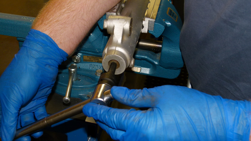
 Now that the inner and outer tubes are nice and clean, stick the outer tube horizontally in the vice and slide the inner tube into it. Slide the tube in and out to make sure there is no binding and use your eye (line the inner tube up with the edge of your bench) to rotate the inner tube to see if there is any misalignment, and therefore see if the inner tube is bent. Remove the inner tube if you’re happy with the fork operation.
 In my last post I showed a picture of the lower section of the inner fork tube where the inner tube bush should go. While we have the two fork sections apart, give this section a close inspection. This area is usually quite worn to the point where the chrome has worn off the leg. No one is going to spring for a new inner tube though right? So either nick or mark the top of the tube where it lines up with the wear so you can reassemble the tube in the triple clamps 90 or 180 degrees so you are on some fresh chrome.
Sound dodgy? Well, it is but the inner tube is pricey from Yamaha, to the point that it might be worth more than the bike. Re-chroming is also an option, I guess it all depends on what sort of maintenance/restoration you intend doing.
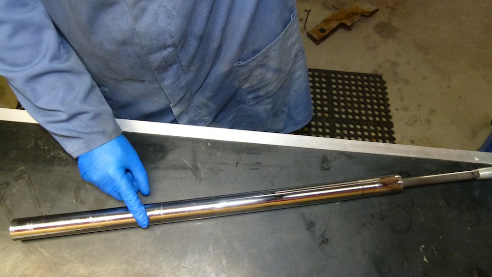
 Use a piece of 2000 wet and dry paper lubricated with fluid (kero, diesel or non-water based wash fluid) to linish the chrome of the inner tube. Rotate the tube while you hold the paper on it so the light marks you leave on the chrome will be at 90 degrees to the movement of the fork tube. You may feel imperfections that you can’t see so if you feel anything big holding up the paper, give the imperfection some more attention, you may need to move up to a heavier abrasive to repair the section so it won’t damage the new seals.
This method will clean up the chrome and make work much easier for the seals. Also clean up the inside of the top of the inner tube where the fork cap screws in. This is where the o’ring for the cap seals the fork – clean is good.
Most corrosion on the inner tubes will be above the area where the inner and outer tubes move, in other words between where the triple clamps hold the forks. It is very common for this to happen on the AG200 and is one reason why I like to assemble the new seals in the outer tube before inserting the inner tube. It prevents damage to the seal by lowering it down over the rusty inner tube. This is contrary to most other methods of fork assembly but I think that a little bit of attention to inserting the seals takes away all these other issues for medium to long term durability of the seal.
Of course another reason is you don’t need a fork seal driver. I have one and can do it this way but since the AG200 doesn’t have a inner leg bush, it all goes together quite nicely and you can insert the seals before assembling the inner and outer tubes and not have to worry about damage. It just means you have to be more vigilant while installing the oil seal. You could of course assemble the fork with dust and oil seals already installed from the bottom of the inner tube to avoid the damaged chrome (assuming it is damaged of course), but it doesn’t leave much room to install the oil seal with a slide hammer without pushing the dust seal up the tube into the damaged chrome in the triple-clamp area. Do what works best for you.
Give your inner tube another clean-up to remove the grit from the wet and dry paper. Give the inside of the outer tube a blast with carby or brake cleaner (careful of paintwork) to make sure it’s all clean. Place the outer tube in your vice, use some rubber grease (normal grease is OK) to lubricate the outside of the seal. Apply a bit to the mating surface in the outer tube as well. Make sure the seal is installed the correct way up (lip spring facing the bottom of the leg)
 Now comes the tricky part, the oil seal MUST be driven in parallel to the outer tube. It must be even as possible without one side of the seal hanging up as it goes down. You only really get one chance to do this right, if you have to pull the seal back up you will wreck it. Patience and being observant will win the day. Some heat on the outside of the outer tube may help with this procedure as well if you have a heat gun.
Use the old seal on top of the new one and drive the new seal down with a hammer.  Take one tap and observe what the seal is doing and try and correct any unevenness as it goes in. When you see the groove in the outer leg for the retaining clip, you are close. The seal needs to be even all the way round and the clip needs to be able to go in, when this is achieved you are done. Install the clip, put some lube on the dust seal lip and install the dust seal. You should be able to do this by hand. This is a good time to get some grease on the oil seal lip as well.
 If you have got this far then most of the work is done. Use some 15Wt. oil to lubricate the damper rod piston and slide it, with the small rebound spring, down the inner tube so the rod slides out the end. Install the spring, washer, spacer and end cap. No need to screw the end cap up too far yet because it’s all coming apart again in a minute.
  Place some oil on the end of the damper rod where the collet fits on the end, fit the collet and use some fork oil to lube the damper rod and the outer tube bush below the oil seal. The inner tube can then be carefully installed into the outer tube.
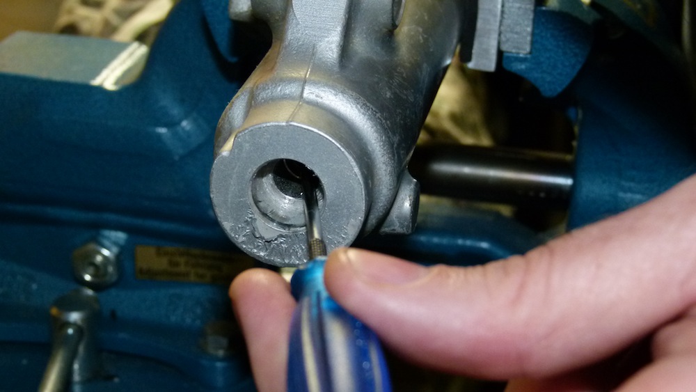
 Looking into the damper rod bolt hole at the bottom of the outer tube, use your pick or a fine screwdriver to align the damper rod with the hole as you push the inner tube down the outer tube. Now the damper rod bolt and the copper washer (renew it if it looks indented or otherwise damaged) can be inserted and done up.
 Because there is no oil in the assembly, you will find that compressing the fork to put pressure on the damper rod to stop it turning, will work much better than when we pulled it apart – no oil = more friction. The Yamaha manual specifies 30Nm torque for the damper rod bolt so if
  you have a torque wrench you can put it to good use here. If not…don’t do it up too tight, 30 Nm isn’t a lot. The Yamaha manual says to use thread locker, I don’t.
Remove the top cap, spacer, washer and spring and check the operation of the fork assembly for smooth and correct operation.  If all is OK place the fork assembly vertically in the vice. Measure out 294ml 15Wt. fork oil and pour it into the fork assembly. I pump the fork up to the top of its travel to the bottom 10 times to pump all of the air out of the system. I then go and have a latte while the air rises out of the oil. You don’t have to do this of course but I love my coffee!
 I then use my oil height tool (117mm from the top of the inner tube to the oil level, fork tube collapsed) to suck out any excess oil. The height of the oil is more important than the volume but you don’t have to get too particular, especially if you don’t have the tools required. Actually I have all the tools that the manual and the experts on Youtube use, but I was also bought up on a farm where we had to make do with nothing. The AG200 can be worked on with minimal special tools and I try to give tips in avoiding them when I can. I realise that most people with these bikes are on a budget, I understand because I was too.
 Extend the fork up to its full height, install the spring (spring free-length should be 403.5mm and no less than 399mm) and make sure the tighter pitch section is at the top. Drop in the washer, spacer and then lube the o’ring and thread on the top cap with a bit of grease and screw it in to the fork. We are finished! All that needs to be done is to tighten up the top cap (23Nm) and can be done in reverse of the Part 1 procedure to undo them. I suggest spraying some chain lube or similar into the hex section of the fork cap before putting the plastic cover back on. Water seems to find its way in under this cap and it will rust pretty bad if you don’t protect it.
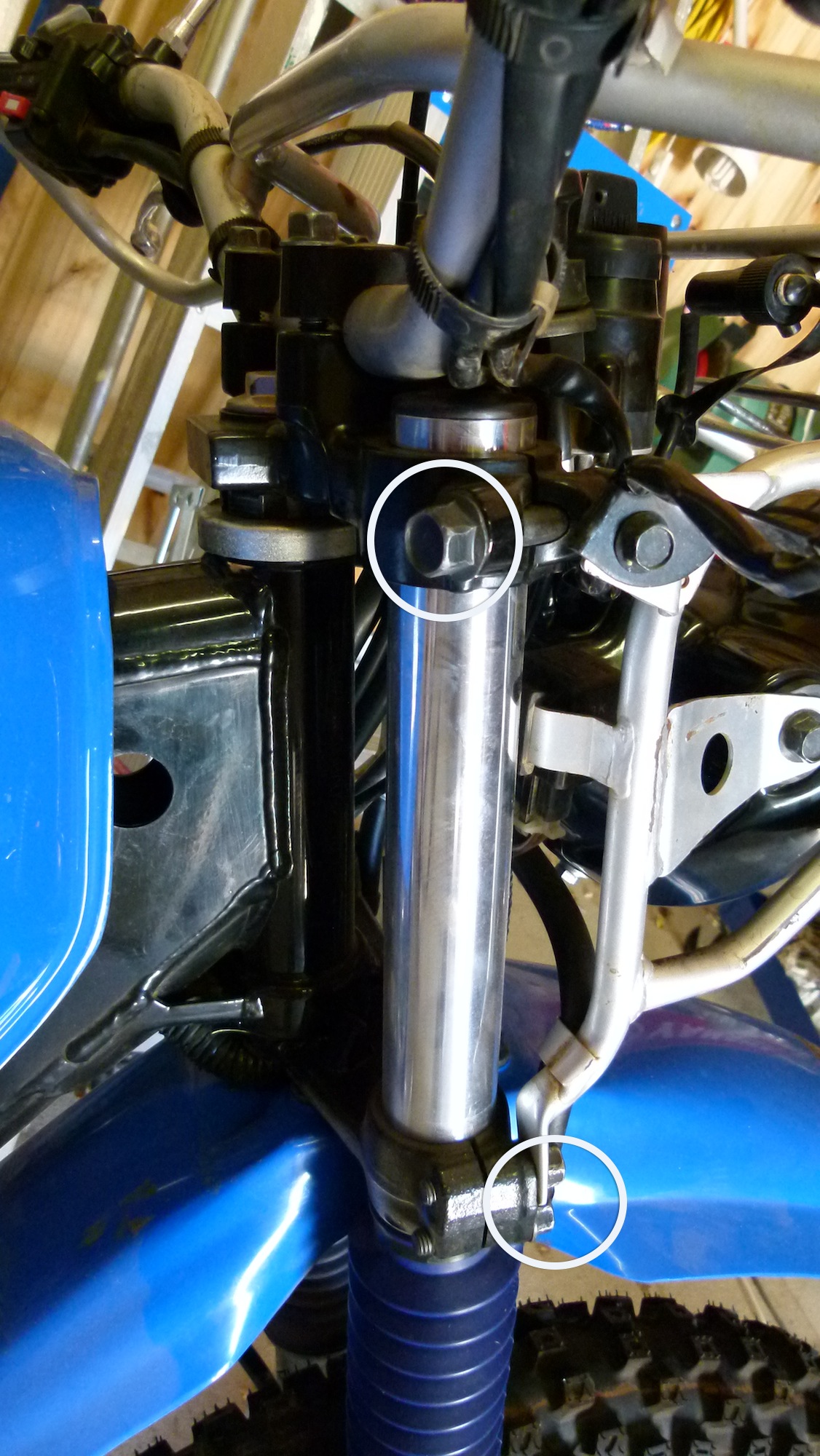
The installation is pretty much the reverse of Part 1 taking note that the top pinch bolt (1 x 14mm bolt & 17mm nut) is set to 34 Nm, while the lower pinch bolts (2 x 12mm) are set to 23Nm. Also take note of the nick or mark that I advised to put at the top of the inner tube as discuss earlier in the blog. As mentioned, if you rotate this mark 90 or 180 degrees you won’t be running on the section without hard chrome.
Also take care aligning the speedo drive up when installing the wheel. If you don’t align it properly, you will bend the speedo drive tabs and it can jam and destroy the whole speedo drive assembly, have seen this many times.
So there you go, all done! Fresh new forks working as they should. Now get that bike back together and enjoy your handy work…
Cheers
AGman
P.S. Like my content? Has it helped you out with your AG200? If it has provided value to you and you would like to help me to continue adding content and information, check out my About/Donate page for info on doing just that! Thanks to those that contribute.


 To me there are only two types of people who own motorcycles (or any other machine for that matter) those that don’t care about maintenance and those that do. I’d say that it is around a 95% to 5% split respectively! Those that do can be broken down again to those that do care, but want someone else to do the spanner work for them, and whose expectations are usually let down by their selected service department, Yamaha or otherwise.